
Hi y'all - I have an Ace 90 project - I’m going to try to use a 94 Wombat engine and pipe on this bike.
Does anyone know if I can safely wire a 94 ignition (stator and primary coil) right into the harness and light components on this bike?
Do I need to find a 94 rectifier or will the Ace 90 rectifier work okay?
Any advice would be appreciated.
Thanks,
-Laurie
P.S. Here’s something cool that came off the Ace 90 (I had not even seen a photo of the original tire pump, so I was pretty “pumped” to find it!)
Ignition Mixing
Ignition Mixing
- Attachments
-
Re: Ignition Mixing
Laurie, I think the Ace 90 rectifier will be fine (same part number 909440 for both the 90 and 94), but you will certainly want to add a Road Toad 6vdc regulator to the mix. The 94 will put out more voltage than the 90 and the lights will not take it without the regulator in place.
Nice find on the air pump.
Dale
Nice find on the air pump.
Dale
Dale
Re: Ignition Mixing
Laurie,
Definitely use the Voltage regulator. And this replacement headlight that I purchased, (it should arrive today), will definitely fit the Ace90 bucket/ring. It's a semi-sealed beam 6v 35/35w halogen H4 bulb. Would make for an inexpensive replacement if the need arises.
Other than the headlight, everything else should be fine. In fact I think the colors from the magneto are the same. If I read the Wiring diagrams correctly, the black wire going to the Coil, also needs to go to the black wire on the key switch. An inline splice may do it. Also, I think the voltage regulator will splice into the brown wire from the key switch. It's a double terminal from the key switch, just change it to a triple.
You might even consider this all in one regulator/rectifier: http://www.regulatorrectifier.com/catal ... -Rectifier
I would be interested in how this project pans out.
Roger
Re: Ignition Mixing
Thanks so much Roger and Dale - great tips. I'll keep y'all posted on the progress (couple of other project bikes ahead of this one).
Roger that headlight sounds like a nice find - hope it works and please keep us updated on the process.
Stay warm folks,
Laurie
Roger that headlight sounds like a nice find - hope it works and please keep us updated on the process.
Stay warm folks,
Laurie
Re: Ignition Mixing
So I think I *might* have the wiring figured out.
Attached is the newly drawn wiring diagram.
My main question is: If I splice the voltage regulator into the brown wire (from HL on key switch) – will this effectively regulate voltage to the headlight and tail light?
The regulator on a 99 ties into an “Emergency SW AC/DC” – I don’t have one of those.
I also don’t have a lot of electrical know-how…
I highlighted the two big changes:
-Addition of the regulator
-Yellow wire connection directly to Dimmer (as directed in Ace 90, but different for 94) In a 94, the Yellow wire from the stator goes to the C2 on the key switch.
Any help would be much appreciated
-Laurie
- Attachments
-
Re: Ignition Mixing
Hi Laurie,
I was looking for this thread just as you posted this comment. because...
I did the same thing last night after studying the diagrams for a couple hours during down-time at work. I studied the wire diagram and the pole positions of the key switch to determine power sources during Day and Night riding respectively.
I modified the file I downloaded from SH tech tips and I came up with the exact same thing with one exception: I put the VR on the Yellow wire. (I'll upload it when I get home). I did this because the battery is already "acting" as a VR for the tail/stop lights.
Between our two diagrams, the only problem I see is:
I have regulated AC current going to the headlights and unregulated current going to the rectifier/battery/stop light. You have just the opposite. Both diagrams will work, theoretically, but ideally, we want regulated current to both circuits but also preserve the dual electrical system, (AC to Headlights, DC to everything else). This is the point I stopped because my brain was beginning to hurt.
Also, the fuse should change to a 15amp fuse rather than the original 5amp since we are hypothesizing a Wombat ignition.
Good work! Helps me feel validated that I am on the right track when two of us come up with the same solution.
Thanks!
Roger
I was looking for this thread just as you posted this comment.
I did the same thing last night after studying the diagrams for a couple hours during down-time at work. I studied the wire diagram and the pole positions of the key switch to determine power sources during Day and Night riding respectively.
I modified the file I downloaded from SH tech tips and I came up with the exact same thing with one exception: I put the VR on the Yellow wire. (I'll upload it when I get home). I did this because the battery is already "acting" as a VR for the tail/stop lights.
Between our two diagrams, the only problem I see is:
I have regulated AC current going to the headlights and unregulated current going to the rectifier/battery/stop light. You have just the opposite. Both diagrams will work, theoretically, but ideally, we want regulated current to both circuits but also preserve the dual electrical system, (AC to Headlights, DC to everything else). This is the point I stopped because my brain was beginning to hurt.
Also, the fuse should change to a 15amp fuse rather than the original 5amp since we are hypothesizing a Wombat ignition.
Good work! Helps me feel validated that I am on the right track when two of us come up with the same solution.
Thanks!
Roger
Re: Ignition Mixing
Laurie, I have some concerns about where the regulator should go in your circuit due to the difference in how the Ace 90 is wired for headlight operation. For the Model 94 Wombat, the HL lead on the key switch would be correct. However, the Ace 90 uses non-rectified voltage directly wired from the magneto to the dimmer switch (Yellow).
So, looking at your diagram, you will have the headlight running directly from the (94) magneto via the dimmer switch (Yellow) without any regulation. And, putting the regulator on HL (Brown) will only serve to regulate the voltage going to the speedo lamp and the tail light.
I need more time looking this all over and I am hoping that others will chime in. In the mean time consider this; If you don't add the yellow lead but instead run the HL (brown) lead to the dimmer switch rather than the yellow?
More to follow unless someone else has this all figured out...
Dale
Dale
Re: Ignition Mixing
Hi Laurie;
In your schematic the regulator is not protecting the headlight. Your schematic shows the headlight power coming from the yellow wire on the magneto via the dimmer switch, so the regulator would need to connect to the yellow wire from the magneto, but this would still be "not quite correct". Refer to the Road Toad wiring diagram. It shows the headlight powered from the green wire from the magneto. The green wire is not switched so the headlight would be on all the time. Regardless, the headlight should be powered from the green wire. On the Road Toad the yellow wire charges the battery through the rectifier, so I think you should connect the yellow wire from the magneto to C1 on the key switch.
To summarize, connect the green wire from the magneto to the yellow wire on the dimmer switch and the green wire on the regulator.
Connect the yellow wire from the magneto to C1 on the key switch.
This will make the system work but your headlight will be on all the time.
I'll try to give you wiring instructions for a regulator and switched headlight later.
Brian
Re: Ignition Mixing
After studying the diagrams for a few more minutes, I think it may be easier than you think to regulate.
The green and yellow wires are both connected to the output of the light coils, it's very possible connecting a VR to either of these will regulate the entire system. The coils appear to be wired in series, so the question is, if regulating one output regulates the other when wired in series. If they were wired in parallel, I would say, yes. But I don't know, when they are wired in series. I'll go ask my local coil expert...
But either way, the Ace 90 circuitry is designed to regulate the green wire output through the rectifier and battery, but you will definitely need a VR on the yellow to the headlight switch.
Roger
Re: Ignition Mixing
Wow, thanks so much Dale and Brian – I’m learning a lot here. So Dale, if they don’t both regulate in series, would it be reasonable to have a second regulator wired into the yellow?
I’m thinking run the yellow wire through a regulator before it gets to the dimmer. Might be a dumb idea, but it would be one way to get both circuits regulated?
I’m not sure if that sort of set up would be a problem elsewhere in the system
Again, thanks so much – I sure appreciate your help!
Laurie
I’m thinking run the yellow wire through a regulator before it gets to the dimmer. Might be a dumb idea, but it would be one way to get both circuits regulated?
I’m not sure if that sort of set up would be a problem elsewhere in the system
Again, thanks so much – I sure appreciate your help!
Laurie
Re: Ignition Mixing
I think we're both learning a lot... (I apologize for the long post, but if you want to get to the point, read the 4th paragraph.)
Still studying and realized something new. I'm beginning to understand what the fine folks at PABATCO did. First, yes the coils are wired in series. Also if you look at the Wombat diagram, you'll see that the green wire is connected between the two coils. And also to the C1 terminal on the key switch. If you study the key switch positions, you realize that C1 is connected to the SE terminal in "Day" operation, which completes the circuit for the rectifier, battery and stop light. Nothing else. This would suggest that since it's connected between two coils in series, the output of the green wire is 1/2 the total wattage of the two coils combined, which would be ~22W. More than enough to run the stop light and charge the battery, which is exactly like the Ace 90 is wired for "Day" operation. The rectifier and battery act as the regulator in this operation mode.
The Yellow wire is connected to the end of both coils and to the C2 terminal. So in the "Night" position, C2 is connected to SE and HL. We know that SE terminal runs the rectifier, battery, and stop light, so we're good there. But HL runs the headlight AND the tail light. Since C2 is connected to the end of the two coils in series, we have doubled the output to about 45W. In the "Day" position, we are only producing ~22W to run the stop light and charge the battery. In the "Night" position, we have doubled our output to ~45W to run the stop light and charge the battery through SE terminal, but we also have UN-regulated AC current to run the headlight/High Beam/ and Tail light through the HL terminal.
Now, looking at the Ace 90 diagram, the SE terminal is not used. Instead, the Green wire is connected directly to the White wire at C1 which goes to the rectifier, at the key switch. We also notice that the headlight circuit is also always on, since the yellow wire goes straight to the Headlight switch. This also means that the Battery charge and stop light circuit are always on if the motor is running. In the "Day" position, there are no terminals connected other than battery to ground, which closes the ignition, stop light, and horn circuits. In the "Night" position, C2 connects to HL which adds the tail light and speedo light to the DC circuit. Remember, the headlight is "always on".
So, to summarize; in order to adapt the Wombat magneto to the Ace 90 wire harness and get the same functionality as originally designed, we need an AC current of ~20W to the green wire at the Ace 90 key switch, The Wombat magneto has a green wire that produces ~22W, so we connect green to green. Now we need another AC current of at least 40W to go directly to the yellow wire of the headlight switch, (assuming we are using a 35W headlight). The Wombat magneto has a yellow wire that produces ~45W, so we connect yellow to yellow. Done. Well.. mostly anyway....
Unregulated voltage is not good on lights, or any electronics, so since the AC current on the green wire is regulated by the rectifier/battery method, we should be OK there. We just need to regulate the AC current on the yellow wire. Simply connect the VR to the yellow wire where it currently connects near the key switch.
btw, remember that yellow/green wire that seems to go nowhere? According to the diagram, it's unregulated 6 VAC @ ~22W in case you want to power an accessory of some sort.
Anyway, that's the results of my studying. I've attached my Ace 90 w/Wombat ignition diagram. So, if you can fit the motor, you can place a 125 Wombat motor in an Ace 90 chassis using existing wiring or if the stator/flywheel fits, you can "upgrade" your Ace 90 ignition with a Wombat ignition.
Roger
Still studying and realized something new. I'm beginning to understand what the fine folks at PABATCO did. First, yes the coils are wired in series. Also if you look at the Wombat diagram, you'll see that the green wire is connected between the two coils. And also to the C1 terminal on the key switch. If you study the key switch positions, you realize that C1 is connected to the SE terminal in "Day" operation, which completes the circuit for the rectifier, battery and stop light. Nothing else. This would suggest that since it's connected between two coils in series, the output of the green wire is 1/2 the total wattage of the two coils combined, which would be ~22W. More than enough to run the stop light and charge the battery, which is exactly like the Ace 90 is wired for "Day" operation. The rectifier and battery act as the regulator in this operation mode.
The Yellow wire is connected to the end of both coils and to the C2 terminal. So in the "Night" position, C2 is connected to SE and HL. We know that SE terminal runs the rectifier, battery, and stop light, so we're good there. But HL runs the headlight AND the tail light. Since C2 is connected to the end of the two coils in series, we have doubled the output to about 45W. In the "Day" position, we are only producing ~22W to run the stop light and charge the battery. In the "Night" position, we have doubled our output to ~45W to run the stop light and charge the battery through SE terminal, but we also have UN-regulated AC current to run the headlight/High Beam/ and Tail light through the HL terminal.
Now, looking at the Ace 90 diagram, the SE terminal is not used. Instead, the Green wire is connected directly to the White wire at C1 which goes to the rectifier, at the key switch. We also notice that the headlight circuit is also always on, since the yellow wire goes straight to the Headlight switch. This also means that the Battery charge and stop light circuit are always on if the motor is running. In the "Day" position, there are no terminals connected other than battery to ground, which closes the ignition, stop light, and horn circuits. In the "Night" position, C2 connects to HL which adds the tail light and speedo light to the DC circuit. Remember, the headlight is "always on".
So, to summarize; in order to adapt the Wombat magneto to the Ace 90 wire harness and get the same functionality as originally designed, we need an AC current of ~20W to the green wire at the Ace 90 key switch, The Wombat magneto has a green wire that produces ~22W, so we connect green to green. Now we need another AC current of at least 40W to go directly to the yellow wire of the headlight switch, (assuming we are using a 35W headlight). The Wombat magneto has a yellow wire that produces ~45W, so we connect yellow to yellow. Done. Well.. mostly anyway....
Unregulated voltage is not good on lights, or any electronics, so since the AC current on the green wire is regulated by the rectifier/battery method, we should be OK there. We just need to regulate the AC current on the yellow wire. Simply connect the VR to the yellow wire where it currently connects near the key switch.
btw, remember that yellow/green wire that seems to go nowhere? According to the diagram, it's unregulated 6 VAC @ ~22W in case you want to power an accessory of some sort.
Anyway, that's the results of my studying. I've attached my Ace 90 w/Wombat ignition diagram. So, if you can fit the motor, you can place a 125 Wombat motor in an Ace 90 chassis using existing wiring or if the stator/flywheel fits, you can "upgrade" your Ace 90 ignition with a Wombat ignition.
Last edited by rlkarren on Thu Jan 16, 2014 6:59 pm, edited 1 time in total.
Re: Ignition Mixing
Well done Roger. I think you have it. Just to clarify, you say the headlight is "always on". I agree that there is always non-rectified AC provided via the yellow wire to the central terminal of the light switch (dimmer switch). This Ace 90 switch has three positions, 0, 1 and 2. Position 0 is off, 1 is high beam and 2 is low beam. As long as you have the Ace 90 dimmer switch, you are good to go.
Dale
Dale
Dale
Re: Ignition Mixing
Hmm, this thing is a little more complicated than I first thought. Roger has done some nice work on this little project and prompted me to dig a little deeper. At first I thought that the Road Toad and Wombat lighting coils were the same, but they're not. They have different part numbers and looking at the coils they have different gauge wire, sooo... forget about my earlier post. It will work with a Toad magneto but not the 94 Wombat. Roger is correct when he states that when the headlight is on, both lighting coils are connected to increase the available power to compensate for the additional load of the headlight and I think his wiring diagram should work.
My only concern is that the Ace 90 uses a 15W headlight and the Wombat uses a 35W headlight. This means that the voltage regulator will be dissipating an additional 20W. The regulator may be capable of dissipating the additional heat, but I would check to see if it is getting hot. You will need to rev the engine for a few minutes and make sure the regulator mounting tab stays under 60 deg C. If it is getting too hot it could fail. If it fails short circuit it will burn up the wiring and/or lighting coil. If it fails open circuit the headlight will likely burn out. Personally I don't think there will be a problem but it won't hurt to check. A 7-8 amp fuse installed between the lighting coil and regulator/headlight might be a good idea. If your Ace 90 is fitted with a 35W headlight than the system should work perfectly.
Brian
Re: Ignition Mixing
Good point Brian. I meant to change the headlight bulb wattage to show 35w. But you're right, a 35W bulb should be used.
I modified my original diagram and replaced it above. I changed the Headlight to a 35W bulb and the fuse with a 15A fuse. I only placed a 15 amp fuse because that's what the Wombat used and I trust the folks at PABATCO knew what they were doing when they designed this schematic.
So the end result, is that if Laurie wants to put a Wombat engine in an Ace 90, this is how you'd do it. I like the idea. Seriously considering doing this myself. Don't forget to use hose clamps to attach the ignition coil. Sometime later this spring, I think I'll experiment putting a Wombat stator and flywheel inside an Ace 90 case.
Thanks for the challenge Laurie. I would be very interested in results of the finished product.
Roger
I modified my original diagram and replaced it above. I changed the Headlight to a 35W bulb and the fuse with a 15A fuse. I only placed a 15 amp fuse because that's what the Wombat used and I trust the folks at PABATCO knew what they were doing when they designed this schematic.
So the end result, is that if Laurie wants to put a Wombat engine in an Ace 90, this is how you'd do it. I like the idea. Seriously considering doing this myself. Don't forget to use hose clamps to attach the ignition coil.
Thanks for the challenge Laurie. I would be very interested in results of the finished product.
Roger
Re: Ignition Mixing
WOW guys - top notch work - this is forum action at its best.
Love the new wiring diagram Roger - many thanks. I’ll get a 35W bulb ordered (thanks to your other lighting posts) and save the original bulb on the shelf.
So the simplest way to tie in the VR is to put a double connector on the yellow wire at the dimmer, one for the VR and one for the yellow coming from the magneto? Just making sure…
Roger, to answer your questions, I did check engine fit yesterday - looks to mount up fine in the frame. I did not play around with mounting an Ace 90 stator on the 94 case.
After wiring, the two other challenges I predict are sprocket alignment and getting the Circle F pipe mounted nicely. Will probably hit some other snags too…
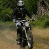
This morning I’m headed out to a friend’s shop (metalworker) to tackle building a flyscreen for the bike (I saw an old photo of an Ace 90 that won a 24 hour endurance race, and it had the coolest little bonnet, racing stripe and all). So this is an effort to recreate that look. Absolutely no function, just fun.
Thanks again to everyone helping me with this project.
-Laurie
Love the new wiring diagram Roger - many thanks. I’ll get a 35W bulb ordered (thanks to your other lighting posts) and save the original bulb on the shelf.
So the simplest way to tie in the VR is to put a double connector on the yellow wire at the dimmer, one for the VR and one for the yellow coming from the magneto? Just making sure…
Roger, to answer your questions, I did check engine fit yesterday - looks to mount up fine in the frame. I did not play around with mounting an Ace 90 stator on the 94 case.
After wiring, the two other challenges I predict are sprocket alignment and getting the Circle F pipe mounted nicely. Will probably hit some other snags too…
This morning I’m headed out to a friend’s shop (metalworker) to tackle building a flyscreen for the bike (I saw an old photo of an Ace 90 that won a 24 hour endurance race, and it had the coolest little bonnet, racing stripe and all). So this is an effort to recreate that look. Absolutely no function, just fun.
Thanks again to everyone helping me with this project.
-Laurie
-
hodakaronwa
- Posts: 13
- Joined: Tue Oct 01, 2013 12:09 pm
Re: Ignition Mixing
You might also consider that the 90 and the wombat stater frame are retained by different size screws? 90 5mm wombat 6mm.
The outer diameter frame may be just a bit larger O.D. than the 90. The taper on the 90 crank "flywheel side" is smaller than the wombat flywheel.
This can all be made to work with the right "Hodaka" part. I have installed the Hodaka CDI to several of the early engines. So I cannot see why the wombat ignition could not be made to work also. You have already received a ton of great info about how to make the 12 volt lighting work. I have a wombat which is street legal which has a 12 volt headlight and the horn,brake light are still 6volt with a battery charging. Works great.
Re: Ignition Mixing
Thanks Ron - really good points, thanks for sharing your experience/knowledge.
And here's what the morning's fabrication turned out:
And here's what the morning's fabrication turned out:
- Attachments
-
Who is online
Users browsing this forum: No registered users and 8 guests