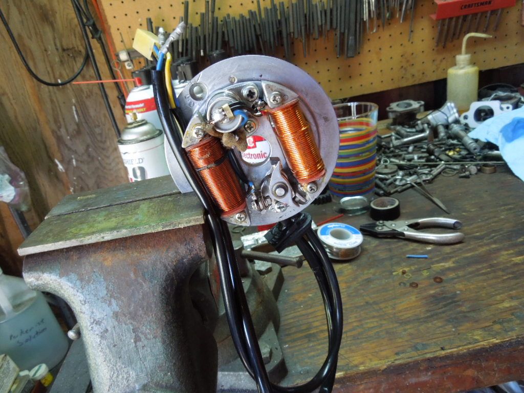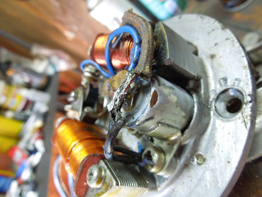
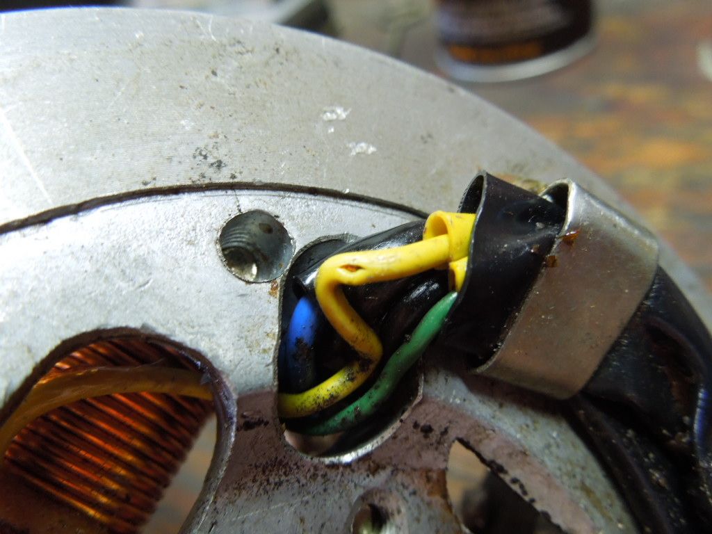
One of the first steps is to remove the wires from the connector in order to replace the black sheathing. The old sheathing is hard and broken in several places.
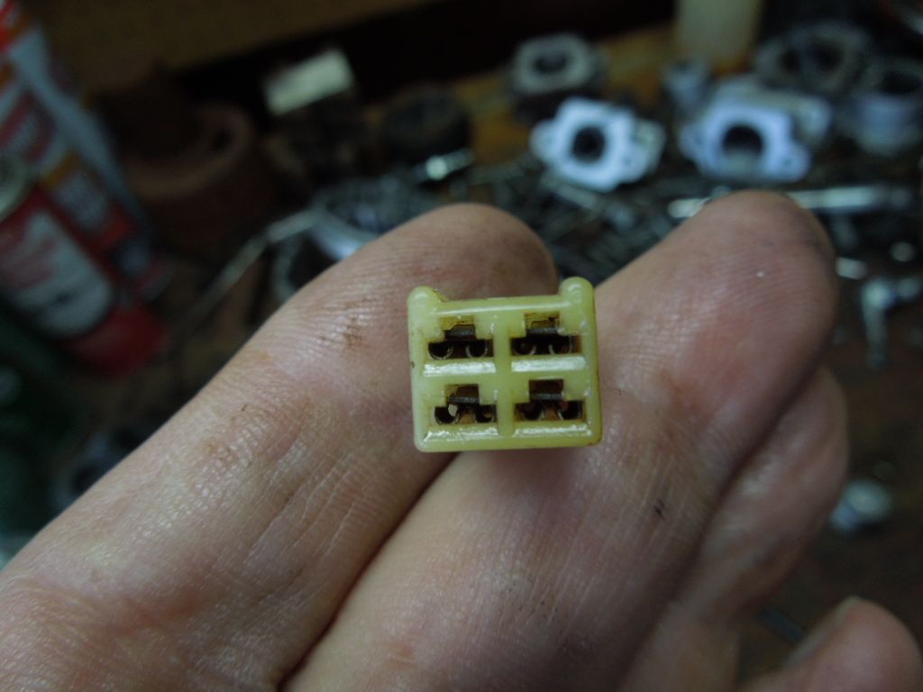
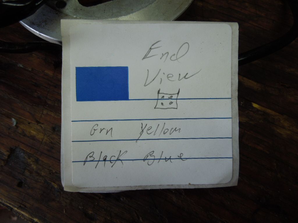
Before removing the wires from the connector I noted the location on some scrap paper.
This tool is used to lighly press the release tang on the wire so it can be removed from the connector.
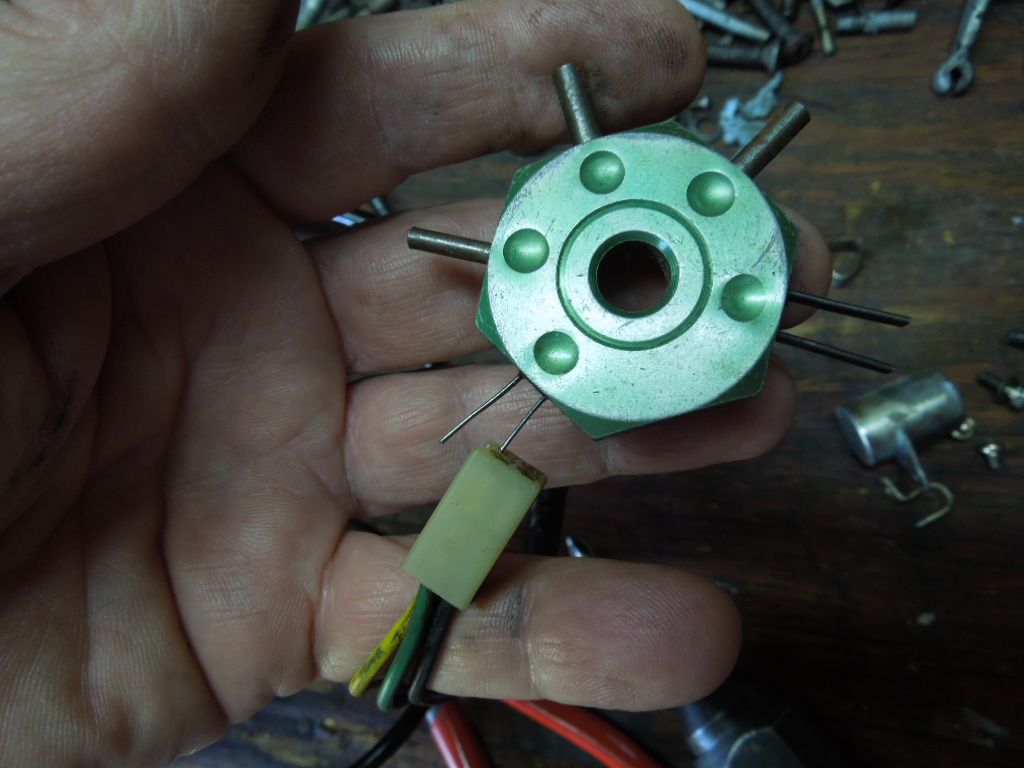
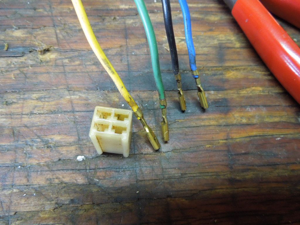
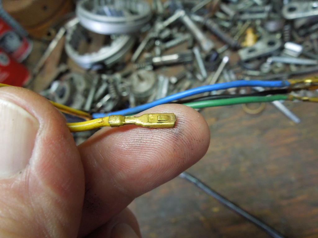
This is the tang that engages the plastic connector. Before re-installing it is usually a good idea to raise it slightly so it engages the ledge in the connector securely.
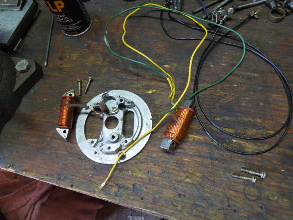
I used CRC electrical cleaner and a soft tooth brush to clean the lighting and exciting coils. This product works well on electrical items and does not damage the coil insulating coating. Automotive brake and carb cleaner should not be used for this task as it can damage the coil coating and some plastic.
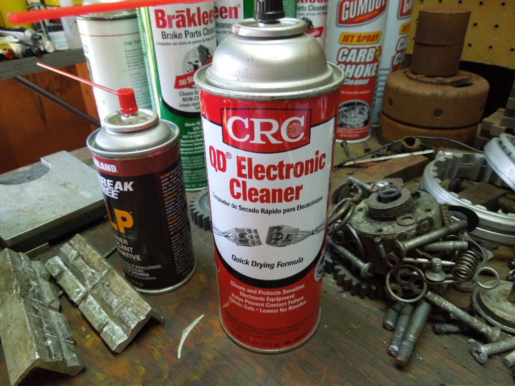
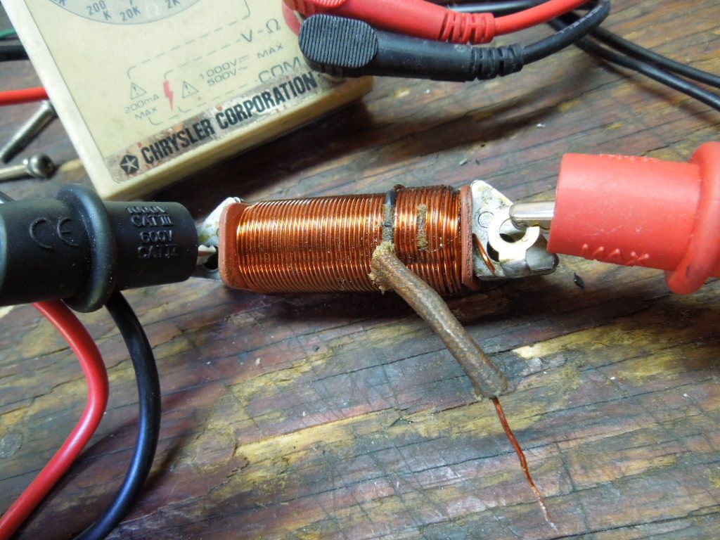
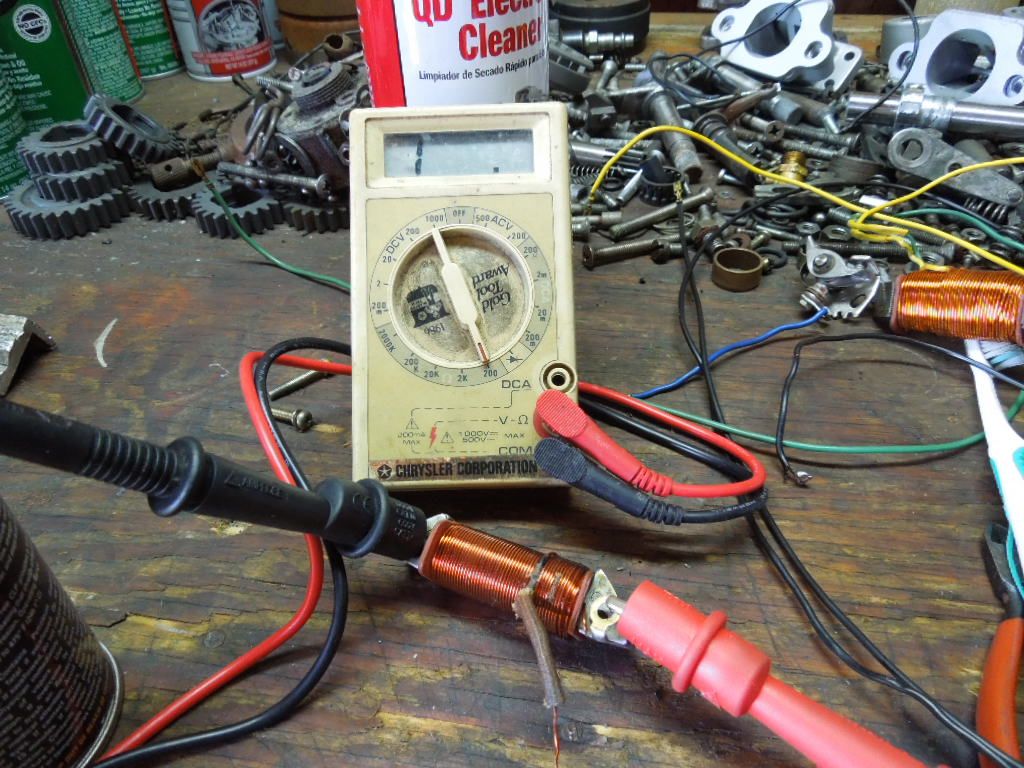
To test the coils I used an ohm meter. For the most part you testing for two things.
1. Continuity of the coil windings. To perform this test the coil wires should not touch the metal core going through the center of the coil. The ohm meter leads are connected to the coil wire ends and the resistance measured. If the meter doesnt indicate any resistance there is a break in the coil windings and the coil will require replacement. Some resistance is expected. My meter indicates .2 ohm when the meter leads are touched together and the .7 measurement displayed would result in a resistance measurement of .5 ohm.
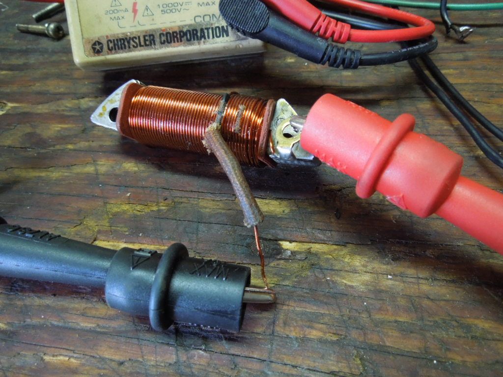
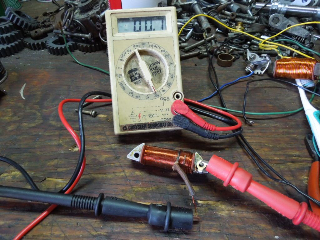
2. Coil windings not shorted / grounded to the metal core in the center of the coil windings. Again this test is performed with the coil wires not touching the center metal core. One of the ohm meter leads is connected to the center metal core and the other lead is connected to either coil wire. No resistance should be indicated / indicate infinity. If any resistance is indicated the coil winds are shorted to the center metal core and the coil will require replacement.
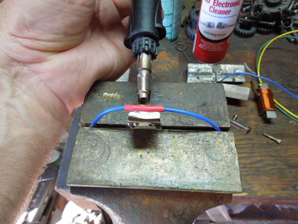
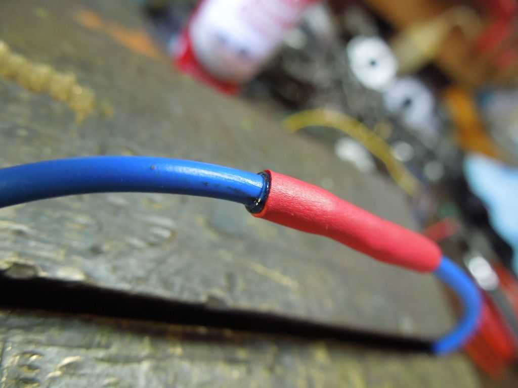
After removing the black sheathing and testing the coils I inspected the wiring and found it to be in good condition and not requiring replacement. While removing the sheathing I nicked the insulation and repaired it and the yellow wire pictured with shrink wrap tubing. The shrink wrap I recommend has an adhesive inside and seals the wire when heated. There are some shrink wrap products that do not have the adhesive and I do not recommend it for out door type projects. When heated properly the shrink wrap will conform to the wire and adhesive will be noted at the end of the wrap.
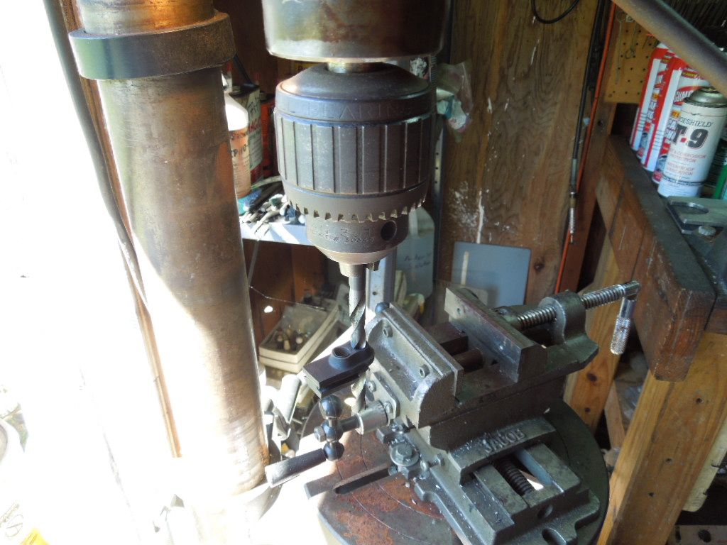
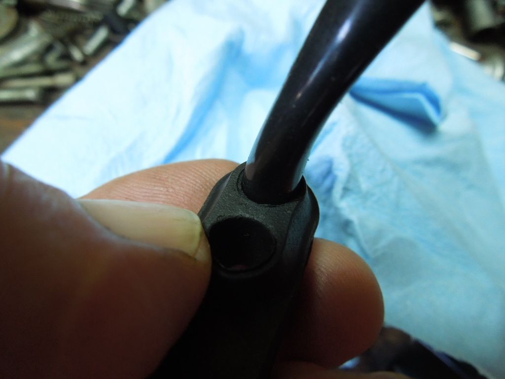
Next thing to do was to address the failed black sheathing. I have not been able to find sheathing that matches the original and have used products from http://www.vintageconnections.com. They have black sheathing in 6mm and 7mm id that works well with some modifications to the rubber wiring grommet. The sheathing is a little larger than the grommet holes and I use the 6mm for the two coil wires and 7mm for the four wire leads. With my drill press set on medium speed, select a drill bit that just fits in the grommet hole. I turn on the drill press and carefully holding the grommet by hand raise the grommet on to the turning drill bit. You will notice little shavings of rubber being removed as you work the grommet up and down over the drill bit. Then move to the next size drill and continue that process until the hole is a snug fit on the sheathing. You will work through several size / steps of drill bits. In this case I ended up with a letter size drill of N and Q.
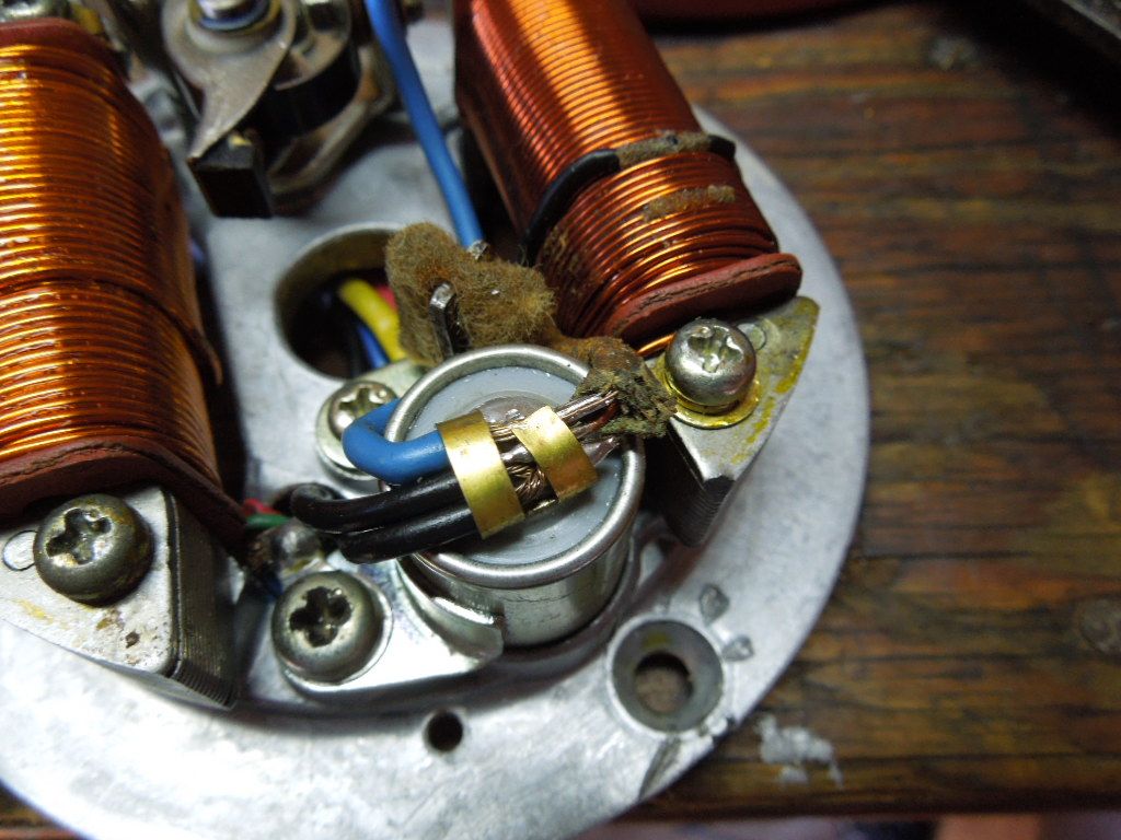
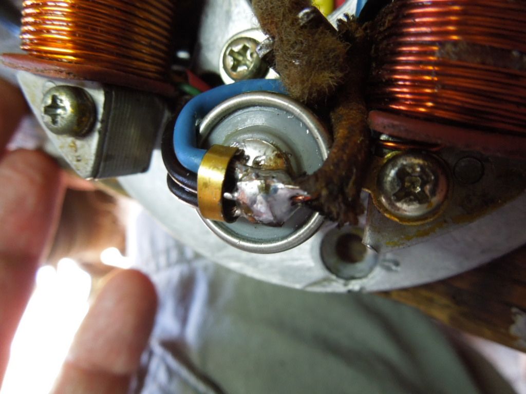
Points do not get too much respect but they are very important to proper ignition operation. Even new points we purchase may be as much as thirty years old..new old stock. You can be sure the grease on the point pivot shaft is dried up and needs replacing. In this case the prior owner had installed new points but somehow I am sure the bike just would not start....see picture one of the condensor solder installation. Any way I cleaned up the point contacts with semi chrome polish and degreased contacts.
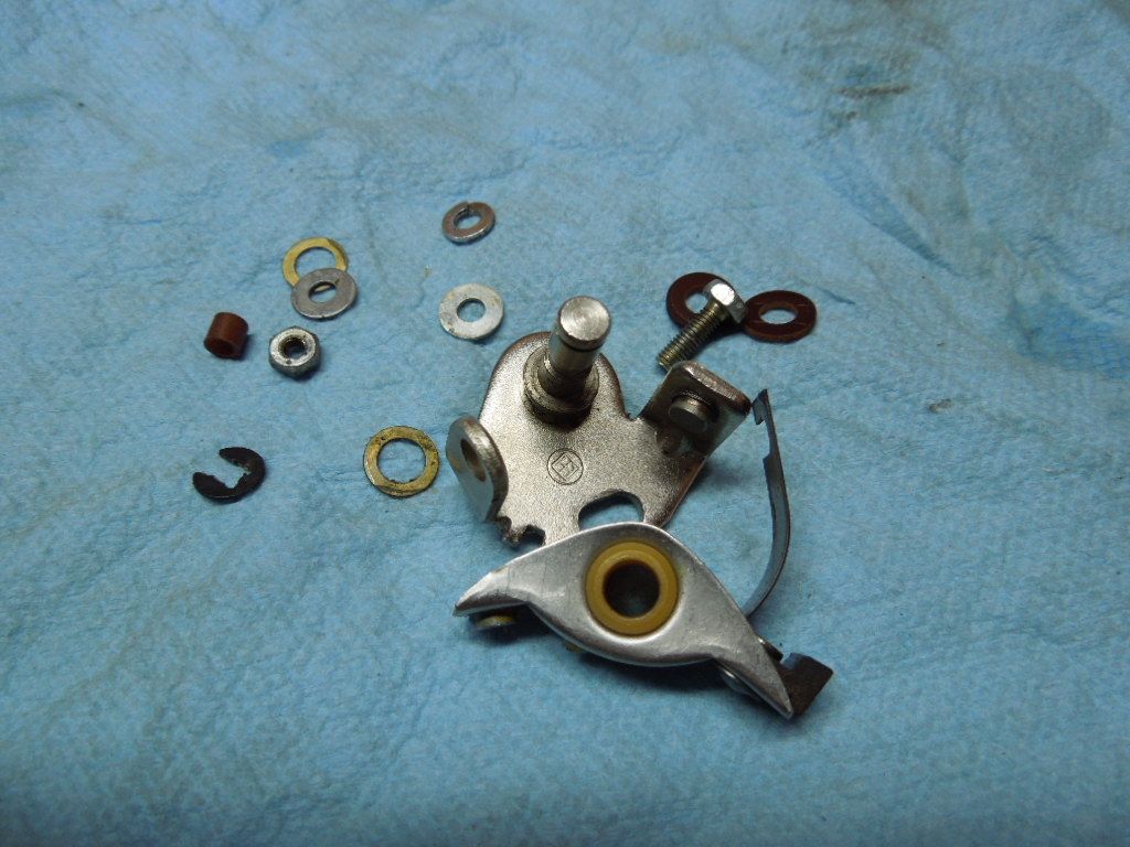
Point contacts should mate squarely and grease applied to pivot shaft


Even though a pad is fitted to lube the point rubbing block I like to apply a light body grease in this area. The idea is as the block wears grease is available for continued lubrication.

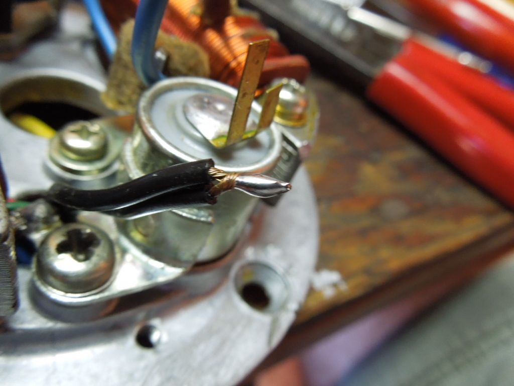
Now it is time to address the condensor soldering issue..new condensor of course. Make sure all wires to be soldererd are clean and oil free. I like to tin all the wires with solder prior to final soldering to the condensor. In this case two of the wires are tinned and soldered together. Pre tinning the wires seems to allow the solder to flow out better in a shorter period of time. This aids in preventing excess heat to the wires and condensor. I used a small diameter rosin core solder and 25 - 400 amp electric soldering gun.
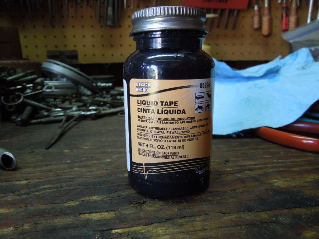
This is liquid tape and I use it to seal the black sheathing to the under side of the wiring grommet. Just a little extra insurance against water intrusion.
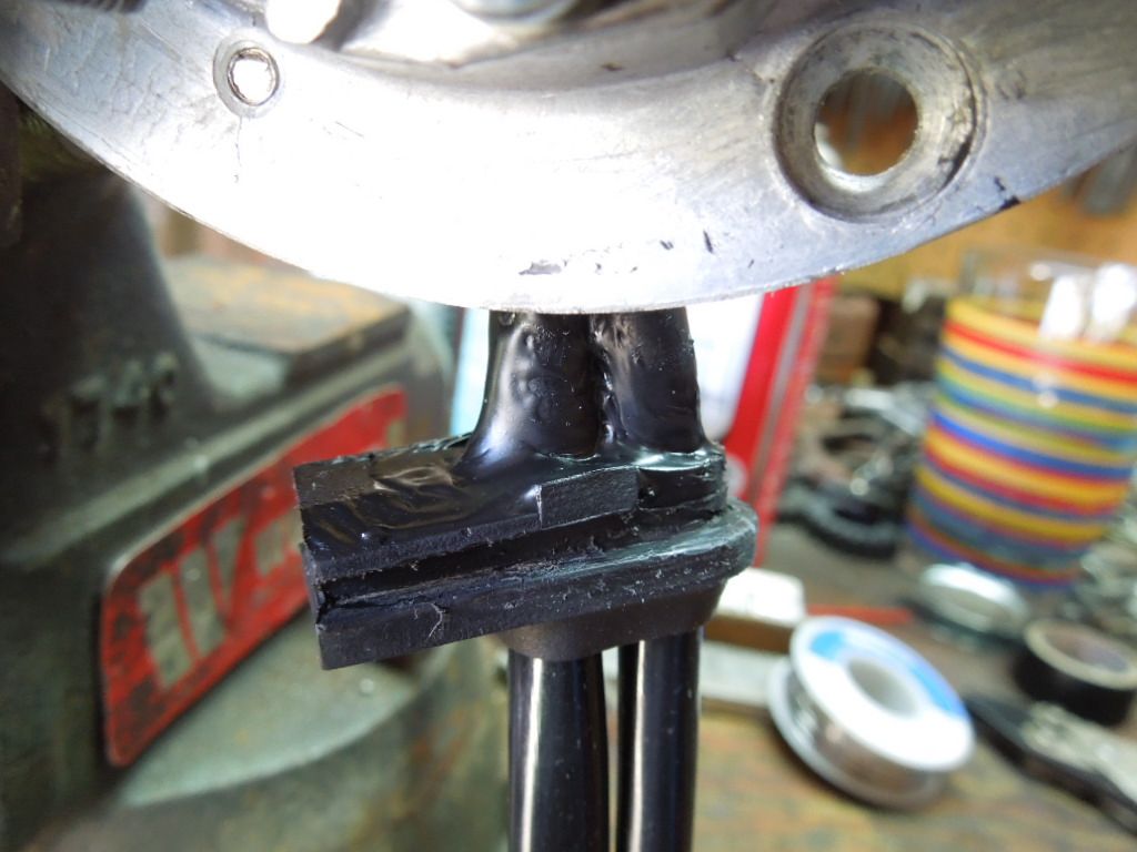
All finished and waiting for the rest of the engine to be completed.
